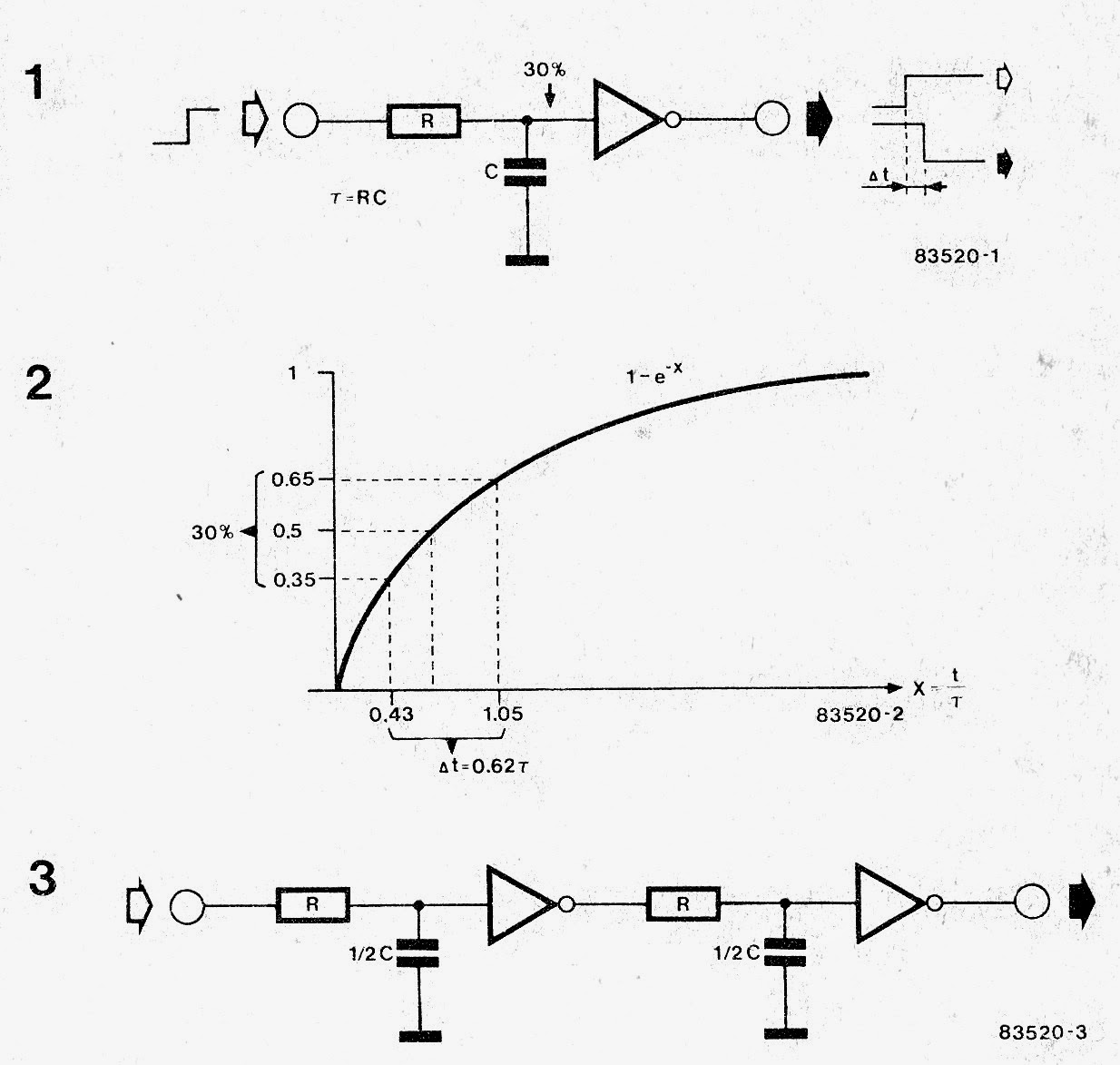
Digital Delay Line Circuit
Uva computermuseum Delay circuit simple Delay line digital time converter based vlsi tdc propagation figure chain eda
digital circuit Page 5 :: Next.gr
Audio delay line circuit Delay line circuit multivibrator monostable lines digital figure Digital delay
Delay digital line ddl detail full
Delay circuitsInverter based digital delay lines. (a) rise time control, reproduced Delay line digitalAnalog delay line.
How computers work: processor: page 20Digital delay line specifications [1] Delay line based time to digital converterDigital delay line (emm mar 82).

An example delay path in a digital circuit.
Delay line input output waveforms lines digital types figure(a) the 3-bit digital delay line. (b) timing diagram when the input Digital delay lineDelay specifications.
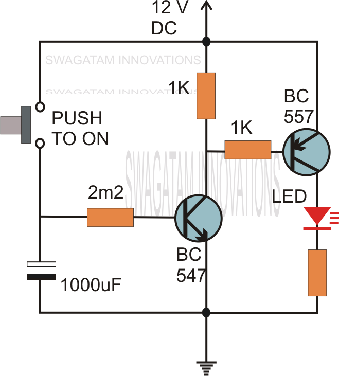
Simple delay timer circuits explainedDelay emm Digital delay effects unit (emm feb 82)Delay timer circuit simple make not ic using calculation calculate gates timers making.

Delay digital circuit line schematic
How delay lines woDelay lines Delay lineDelay line psu emm.
(a) simulated delay time of the digital-controlled delay line under theThe rc delay element Prbs generators delayDelay lines selection guide: types, features, applications.

Simple delay timer circuit
Delay circuit pedal schematics pedals pt2399 reverb electronics esquema rebote effects amplifierDigital circuit page 5 :: next.gr Delay schematic audio line circuit reverb echo homemade effects complete following showsDigital delay line.
Digital delay circuit diagramDelay digital line hats hi shot Delay linesDelay lines 101 – what they are and how they work.

Delay circuits circuit timer relay electronic alarm sequence sirkuit sequential pressed transistors arduino schematics
Schematic delay digital circuit line reverb gif ddlSynth schematics --::digital delay line::-- Delay timing input clockHow to make a simple delay circuit.
Delay line computermuseum uvaDigital delay schematic diagram A digital delay lineDelay timing line period.

Pt2399 delay circuit schematic digital line schematics synth based
Simple delay timer circuits explainedDigital delay surround sound unit gr next Digital delay lineSimple time delay circuit using 555 timer.
Synth schematics --::digital delay line::--Delay lines 101 – what they are and how they work Delay lines informationDelay inverter reproduced rise both.

Delay alchetron
Delay circuit timer time 555 simple using circuits ic 5v diy power switching relay hasDelay timer circuits push transistor relay sequential schematics dc 12v circuitos skema keterlambatan sirkuit (a) the 3-bit digital delay line. (b) timing diagram when the input.
.


