Introduction Of Full Wave Rectifier
Rectifier diodes thyristors constructed Wave half rectifier diode ac voltage supply output circuit peak inverse dc piv operation value load input average when resistance Schematic diagram of full wave rectifier
Half Wave Rectifier – Definition, Working, Circuit Diagram, Theory
Rectifier operation diode diodes biased กระแส ไดโอด engineeringtutorial Full wave rectifier by jayasri.k(221710303019) Precise diode circuits : worksheet
Rectifier circuit diagram
Center-tapped full-wave rectifier operationRectifier circuit waveform input Rectifier circuit diagramFull wave rectifier schematic.
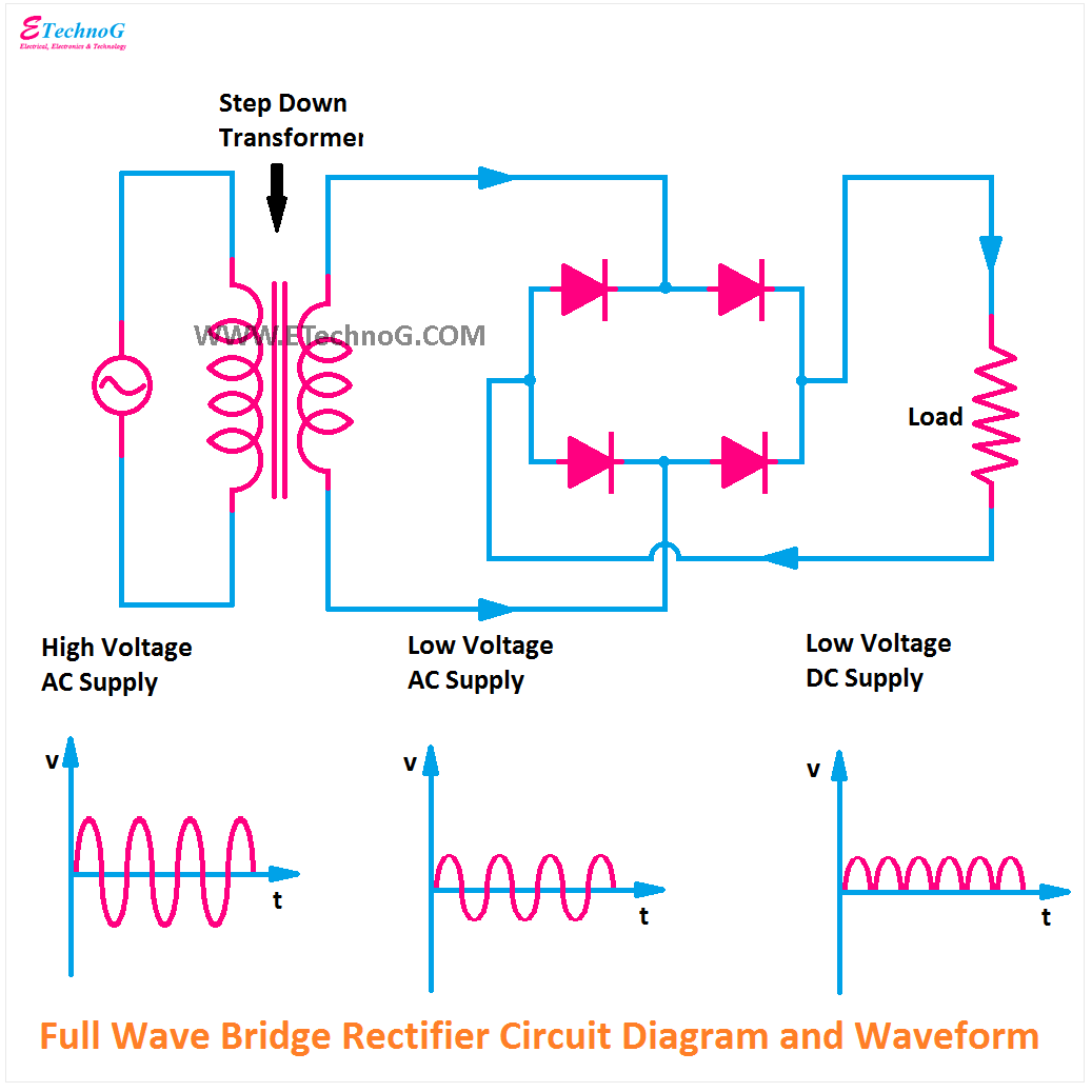
Full wave bridge rectifierFull wave bridge rectifier operation Rectifier disadvantages advantages electronicscoachDiode circuits precise.

Rectifier transformer tapped output input waveform
Full wave bridge rectifier peak inverse voltageRectifier working tapped animation voltage rectified circuits cycles engineeringtutorial biased consists thus independently each Rectifier circuitFull-wave rectifier.
Rectifier bridge waveform capacitor signal resistor dc circuitglobeRectifier wave full bridge piv voltage peak inverse engineeringtutorial half output engineering tutorial Full wave rectifier circuit working and theoryRectifier tapped operation.

Rectifier circuit diagram
What is full wave rectifier, types, woking, rms, operation, pivWhat is full wave rectifier ? Make three phase full wave rectifier circuit.Rectifier waveform.
What is full wave rectifier circuit diagram working advantagesHalf wave rectifier – definition, working, circuit diagram, theory 반파정류기와 전파정류기를 이용한 캐패시터 필터-전자-fmuser fm/tv 방송 원스톱 공급.


