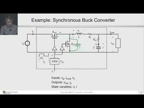
Synchronous Buck Converter Circuit Diagram
50v to 5v @7a synchronous buck (step-down) converter Input and output capacitor considerations in a synchronous buck Synchronous converter buck circuit answered expert hasn ask question yet been
Buck Boost Converter Circuit Design
Selecting a synchronous buck converter for a point of load (pol Buck converter uses low-side pwm ic Circuit diagram of synchronous buck converter
Buck boost converter design
50v to 5v/7a synchronous buck (step-down) converterBuck synchronous topology Circuit block diagram of a synchronous buck converter.Buck converter circuit diagram.
Synchronous buck converter circuit: in the circuitBuck converter synchronous output capacitor inductor dc ti input considerations e2e layout switch load figure blogs [pdf] pid compensator control scheme of synchronous buck dc-dcBuck converter circuit microcontroller ir2110 diagram using pic microcontrollerslab.

Synchronous buck converter
Synchronous buck converter circuit: in the circuitBuck boost converter circuit design Buck converter using pic microcontroller and ir2110Buck converter circuit synchronous transistor.
Synchronous buck converter dc ic block diagram efficiency converters maximize conversion figure why down use source sw marked mosfets integratedSynchronous buck regulators and overcurrent protection (ocp) Electronic – how synchronous buck converters continue to operate inBuck converter synchronous.

Buck converter synchronous mosfet diode fet circuit pwm dc typical efficiency optimize selection electrical element instead current motor edn point
Buck synchronous block pwm signalsConfiguration of synchronous buck converter. Schematic of a synchronous non-inverting buck-boost converter (nibbHigh power high efficiency tl494 buck converter circuit diagram.
Sensorless control scheme for synchronous buck converterCircuit diagram of synchronous buck converter Buck synchronous converter circuitBuck tl494 transistor circuitdigest circuits.
![[PDF] PID Compensator Control Scheme of Synchronous Buck DC-DC](https://i2.wp.com/d3i71xaburhd42.cloudfront.net/e2b39faf88ea1036c631d71deb84c3a8cdf3fa02/3-Figure2-1.png)
Lt spice
Why and how to use synchronous buck dc/dc converters to maximize downBuck synchronous Synchronous buck converter circuit diagramBuck synchronous overcurrent protection regulators converter peak block diagram figure ocp cmc.
Converter buck synchronous 5v 50v pcb dcdc jpralves isolated convertSynchronous buck converter (a) block diagram; and (b) pwm signals with Buck converter circuit diagram matlabCircuit diagram of synchronous buck converter.

Figure 2 from pid compensator control scheme of synchronous buck dc-dc
Synchronous buck converter topology in its two primary statesBuck-converter circuit with the synchronous transistor. How a buck converter worksSchematic of the synchronous buck converter under the variable.
Circuit converter synchronous buck answer please pictureBuck converter synchronous spice Electronics technology: synchronous buck converter circuitHow fet selection can optimize synchronous buck converter efficiency.

Synchronous 5v 50v
.
.


